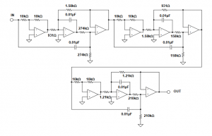
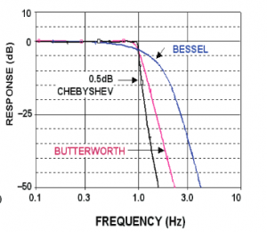
Overview of filters
If it is not obvious, I think it is best to share that I’m an engineer. One area I have liked since being exposed at a deep level is filter design and applying this to conditioning electrical signals. Examples of why signals need filters include:
- Signals are often acquired by an analog to digital converter, which has a fixed sampling rate such as 1kHz (1ms). If there are any frequencies greater than 1/2 the sampling frequency, these higher frequency components ‘leak’ back in as aliased signal content.
- There is a component of noise within the signal that needs to be removed, such as interference from a nearby component that is emitting an interfering signal at a well-defined frequency.
Filter design isn’t a large part of my job (and as CTO probably should not actually be any part of my job), but it does come up every few years.
Zooming into my immediate observations
It is the latter example that I’ve spent some time exploring over the last few days. There is a particular frequency component that needs to be removed. What I have been surprised about, is there are no better tools available on the internet to help me design a filter for this?! While there are calculators available, there are no better actual design tools to help me optimize a filter than there were when I last designed a filter 10+ years ago. Even the TI Filter Design tools seemed the same as they were, but only worse as I never actually even received a solution for the filter I was trying to design. About the only positive thing I found, is Analog Devices has their Filter Design book online such that I didn’t have to pull out my printed copy.
Manual solution
When designing a filter, I have a rather well-defined path:
- I consider the signal I want to remain.
- I quantify the noise that needs to be filtered and how much should be remaining: The amount of attenuation in dB is: -20log10(Filtered Magnitude /Unfiltered Magnitude).
- I define the passband characteristics (how flat the filter should be away from the filtered region) and where I can accept the filter starts to influence the signal.
- Based on this, the filter order and shape can be quantified.
- The filter response can be plotted.
- The signal with noise can be fed into the filter in which the output can be simulated.
Once we have this information, the filter can be designed. What I was surprised about, is that in particular for a notch filter, I didn’t find an easily available tool that just spelled this out for me. I either put some basic terms into calculators that gave me component values and only a graph of the response or I would note the long equations not linked to how the values of the components are calculated. Neither provided a direct means to allow me to simulate the actual signal.
I ultimately turned to the Analog Devices filter book and used a Jupyter Notebook and Python to derive the filter equations, plot the responses, calculate the component values, and then provided graphs of my simulated output. At some point, I’ll leave an additional post about exactly how to do this with actual values that can be checked for others (or myself in the future) that need to go through these same exercises themselves.

Source: Analog Devices

